The 4 pin mass air flow sensor plays a critical role in modern automotive engines by measuring the amount of air entering the combustion chamber. Positioned between the air filter and the throttle body, this sensor provides essential data to the engine control module (ECM), enabling precise calculation of the fuel required for optimal combustion.
During colder months, denser air increases fuel injection, whereas warmer engine conditions result in lower gasoline consumption. This dynamic adjustment ensures efficient engine performance across varying conditions.
Understanding the wiring schematic of an MAF sensor is crucial for accurate diagnostics, sensor testing, and maintenance tasks. This knowledge proves especially valuable when dealing with oxygen sensors, as a well-informed approach can save both time and money.
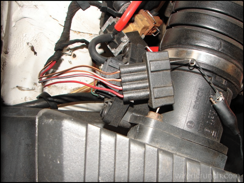
In this powerful article, you will quickly learn the 4 pin mass air flow sensor wiring diagram schematic, empowering you to handle related automotive tasks with confidence and precision.
Table of Contents
How Your Car Measures Airflow
The Mass Airflow (MAF) Sensor works by measuring the mass of air entering an engine’s intake system. Typically located in the air intake tube or air filter box, it uses a hot connector or hot film element that is cooled by incoming air. As air passes over the hot element, the temperature drops, which helps determine the mass of the airflow.
This information is then processed and sent to the vehicle’s Electronic Control Unit (ECU). The 4 Pin mass air flow sensor plays a crucial role in indicating the amount of air reaching the consumption manifold, allowing the ECU to adjust gasoline delivery for optimal ignition efficiency.
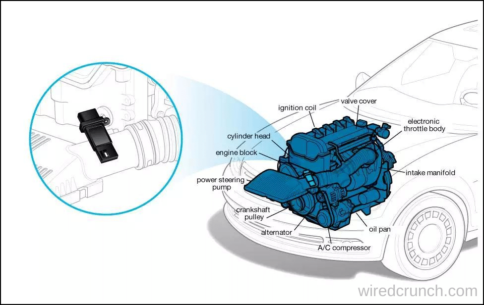
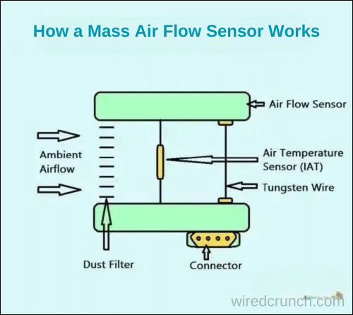
How a Mass Air Flow (MAF) Sensor Works
A mass airflow (MAF) sensor works by measuring the current flow needed to keep a tungsten wire warm as air passes over it. This principle helps determine the mass of air flowing into the engine. Inside the air cleaner assembly tube, the MAF sensor includes a dust cleaner, an intake air temperature sensor, and a tungsten wire. As air enters the engine, it cools the wire, requiring more electricity to maintain its temperature. The sensor processes this information and sends it to the engine’s control unit to adjust fuel delivery for optimal performance.
Mass Air Flow (MAF) Sensor Function
The basic function of a mass airflow (MAF) sensor is to measure the rate of airflow entering a car’s engine. This measurement is essential for the Engine Control Unit (ECU) to determine the correct amount of fuel to inject into the cylinder. Older MAF sensor models used a heated wire that would switch off the engine after reaching a certain temperature. In contrast, newer models use a film-like sensor or heat resistor that can handle temperatures up to 120 to 180°C, with the incoming air cooling it down. Additionally, the latest MAF sensors feature pulsation and return flow functions for more precise measurements and improved engine performance.
Mass Air Flow (MAF) Sensor Wiring Diagram
The wiring diagram for a mass airflow (MAF) sensor can vary based on the year, make, and model of the vehicle. Manufacturers design the cabling schematic of the MAF sensor according to the specific needs and demands of each vehicle.
In this powerful guide, we will provide a general overview of how MAF sensor connections are typically designed, rather than focusing on specifics. For detailed information specific to your vehicle, it’s best to consult your car owner’s manual.
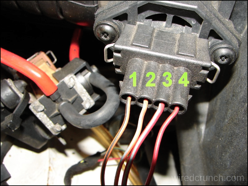
Keep in mind that the connectors are often color-coded differently depending on the brand and type of sensor used in your vehicle.
4 Pin mass air flow sensor wiring diagram Explanation
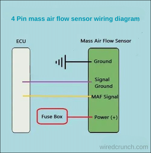
A 4 Pin mass air flow sensor has four wires:
- 12 Volt Feed Positive Power
- MAF Cord Ground
- MAF Signal Ground
- MAF Signal
A 4-wire mass airflow sensor has a 12-volt positive battery voltage connected to the fuse box’s fuse and relay in the connector. The MAF signal wire sends the output voltage to the car’s electronic control unit (ECU). A four-wire MAF sensor also has two separate grounds: one for the hot feed wire, earthed somewhere in the chassis, and another for the MAF signal circuit, which is also sent to the ECU.
The MAF sensor’s signal circuit calculates the current flow to the sensor, converts it to voltage, and sends this information through the MAF signal wire. For detailed understanding, the 4 Pin mass air flow sensor wiring diagram shows how these connections are typically arranged and helps in proper diagnostics and maintenance.
Conclusion
Understanding the 4 Pin mass air flow sensor wiring diagram is essential for proper vehicle maintenance and diagnostics. This diagram shows the connections for the 12-volt positive power, ground wires, and signal wires, all of which are critical for the MAF sensor to function correctly. Knowing the specifics of these connections can help you troubleshoot issues, ensure accurate sensor readings, and maintain optimal engine performance. Always refer to your car’s owner’s manual for the exact wiring diagram for your specific make and model to save time and avoid potential mistakes.
Frequently Asked Questions (FAQs)
What is the voltage of the MAF signal wire?
An output signal of MAF, made by BOSCH is a variable voltage in the range of 1 – 5V, whose value depends on the mass of airflow through the sensor. At zero airflow (engine stopped) the sensor output voltage should be equal to 0.98V – 1.02V.
What is the code for the MAF sensor low voltage?
What Does Code P0102 Mean? The MAF sensor is generally positioned downstream of the air filter in the air intake system. It measures both the density and volume of air passing through your intake and into the engine. A P0102 error code means that there’s insufficient air traveling through your air filter.
How to troubleshoot an MAF sensor?
You can also maintain the engine at specific RPMs to test the MAF sensor readings. For instance, at 2500 RPM, the value should be greater than at idle but lower than at 4000 RPM. If the live data doesn’t follow this pattern, it indicates that your Mass Air Flow Sensor may be dirty or malfunctioning.
What happens if you unplug a mass air flow sensor while running?
If the MAF sensor is bad or unplugged, the computer of the engine will use a programmed default strategy to control fuel flow. That could result in a high idle. Depends on the program for your car.
How many ohms is an MAF sensor?
Typically, the power wire is red and the ground wire is black. However, you should confirm this with the wiring diagram to be sure. The multimeter should read between 200 and 600 ohms. If the resistance is either too high or too low, it indicates that the MAF sensor is defective and should be replaced.
What would happen if the mass air flow (MAF) sensor stopped working? Would it be possible for it to start working again on its own, or would it need to be removed and reset?
If the mass air flow (MAF) sensor stopped working, it could lead to a variety of issues with the vehicle’s performance.
READ MORE:
How to Get Oxygen Sensor Monitor Ready
I have a professional background with a Diploma in Information Communication Technology, which brings a blend of technical expertise and creative flair to my writing. Currently, I serve as a writer for Creativeoutrank LLC and contribute to their various websites.
I’m writing is a ref... Read more


