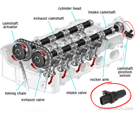
The camshaft position sensor diagram is a crucial visual aid in understanding the functionality of the camshaft position sensor within modern internal combustion engines. This sensor, pivotal in accurately determining the rotational position of the camshaft, plays a fundamental role in engine performance and efficiency.
Monitoring the camshaft’s position is critical for the engine control unit (ECU) to adjust ignition timing and synchronize fuel injection events precisely. This process optimizes engine performance, enhances fuel efficiency, and aids in controlling emissions.
Exploring the camshaft position sensor through a detailed diagram provides insights into its placement, electrical connections, and how it interacts with the engine’s timing system.
Whether preparing for examinations such as SSC JE ME and RRB JE Mechanical Engineering or seeking a deeper understanding of automotive technology, this article aims to uncover comprehensive information about the camshaft position sensor and its vital role in modern engines.
Table of Contents
What is a Camshaft position sensor?
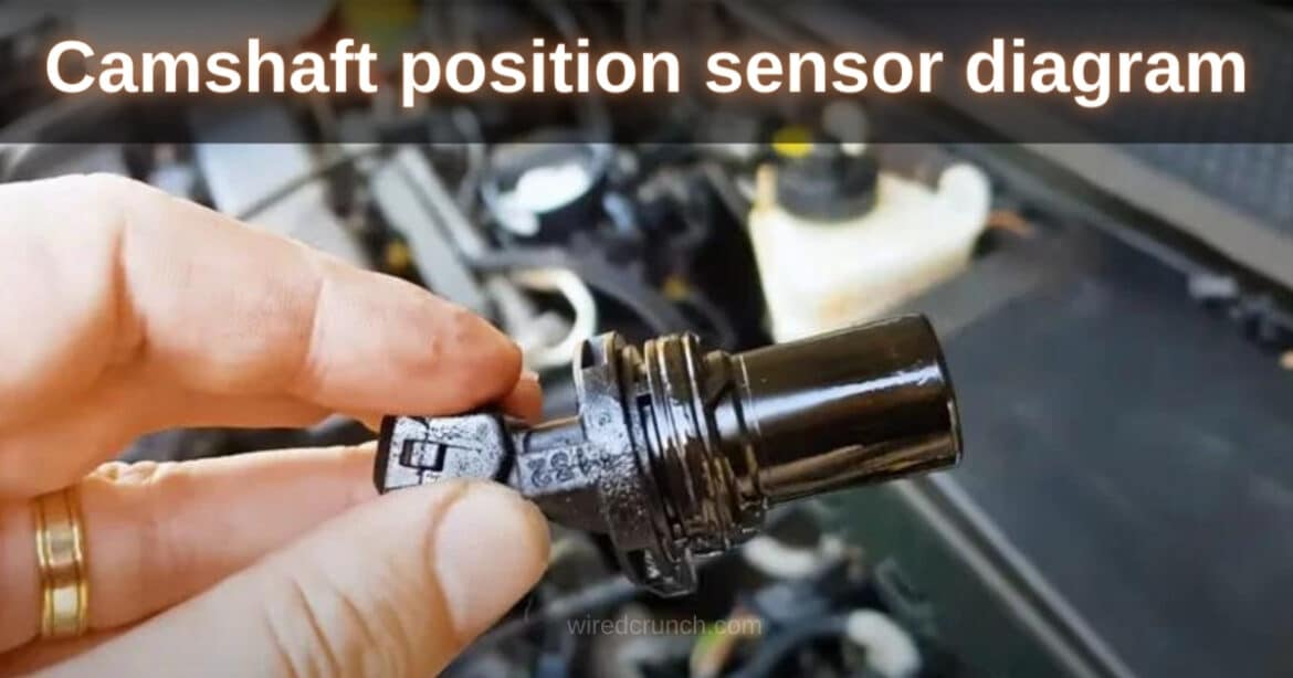
The camshaft position sensor is an electronic component used in engines to measure the rotation and orientation of the camshaft. It sends this information to the engine control module (ECM). The ECM uses this data to control the timing of the spark and fuel delivery, which is crucial for optimizing engine performance. This precise timing ensures efficient combustion, leading to increased engine power, better fuel economy, and reduced emissions. In modern engines, the camshaft position sensor also identifies the specific cylinder’s power stroke about the crankshaft’s position.
This information is essential for supplying fuel and sparks, especially when starting the engine. Typically, the camshaft position sensor is a small magnetic device mounted near the camshaft or camshaft pulley, often found on the cylinder head or timing cover of the engine.
Functions of the Camshaft Position Sensor (CAM)
Here are the common functions of a camshaft position sensor:
Monitoring Camshaft Position:
- The camshaft position sensor monitors the rotating position of the camshaft relative to the crankshaft.
Determining Cylinder Power Stroke:
- It helps the car’s computer determine which cylinder is on its power stroke.
Providing Data to ECM:
- The CAM sensor informs the engine control module (ECM) of the camshaft’s position.
Adjusting Spark Timing:
- The ECM uses the information to alter the spark timing.
Controlling Fuel Injector Operation:
- The sensor’s data is used to adjust the fuel injector operation for optimal performance.
Synchronizing with Crank Sensor:
- The camshaft and crankshaft sensors work in sync with one another.
Sequential System Operations:
- In sequential systems, the CAM sensor determines which injector to fire.
Managing Coil-On-Plug (COP) Ignition:
- It is also responsible for the coil firing event in the COP ignition system.
These steps ensure efficient engine operation, better fuel efficiency, and reduced emissions. The camshaft position sensor collects and sends data about the camshaft’s speed to the engine control module (ECM). The ECM uses this information to determine the ignition timing and the timing of fuel injection needed by the engine. Without this information, the engine would not work effectively.
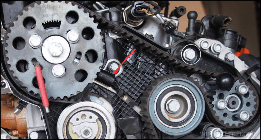
Camshaft position sensor diagram explanation
Working Principle of Camshaft Position Sensor
The camshaft position sensor plays a crucial role in engine operation. In a sequential fuel injection system, it helps the engine control unit (ECU) determine which cylinder to ignite next. The sensor sends a signal to the onboard controller each time the first cylinder reaches the top dead center (TDC) during engine rotation. This signal allows the ECU to calculate the pulse injection duration accurately. In simultaneous fuel injection systems, the onboard controller doesn’t need to identify specific cylinders or the firing sequence, as it’s not essential for the system’s operation.
The specific cylinder is identified when a signal for crankshaft or distributor advance ignition is received, using mechanical cues from the crankshaft, camshaft, valves, or distributor shaft. The camshaft position sensor ensures smooth and efficient engine performance by providing precise timing information.
Symptoms of a Bad Camshaft Position Sensor
Here are the symptoms you might experience when a camshaft position sensor is faulty:
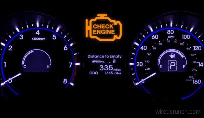
Check Engine Light is On:
When your camshaft position sensor fails or malfunctions, the first thing you’ll notice is the “Check Engine” light on your dashboard. While this light can indicate various issues, a faulty camshaft position sensor is one possible cause.
Ignition Problem:
If the camshaft position sensor fails while you’re driving, the engine may lose power, causing your car to shake or randomly surge forward. This happens because the PCM receives inaccurate information from the camshaft position sensor, leading to the wrong amount of fuel being pumped into the cylinders.
Engine Stalling:
Worse than not being able to start your car is having the engine shut down or stall while driving because the fuel injectors aren’t being instructed to supply fuel to the cylinders.
Poor Acceleration:
When your camshaft position sensor starts to fail, your vehicle will jerk and struggle to accelerate quickly. Sometimes, you might not be able to go faster than 30 miles per hour. This weak acceleration is due to the injectors supplying the incorrect amount of fuel.
Problem Shifting:
In some car models, a faulty camshaft position sensor can cause the transmission to lock in a single gear. The only way to shift out of that gear is to turn off the engine, wait a few moments, and then restart it.
Bad Fuel Mileage:
A faulty camshaft position sensor can cause too much fuel to be pumped into the engine, leading to poor fuel economy. This happens because the sensor gives an incorrect reading, causing the engine to receive more fuel than necessary.
Steps to Change a Camshaft Position Sensor
Changing a camshaft position sensor isn’t too complicated, but you’ll need some basic tools and a code reader to do it correctly.

1. Disconnect the Negative Battery Cable
Before working on the electrical system or engine, disconnect the battery to prevent accidental short circuits.
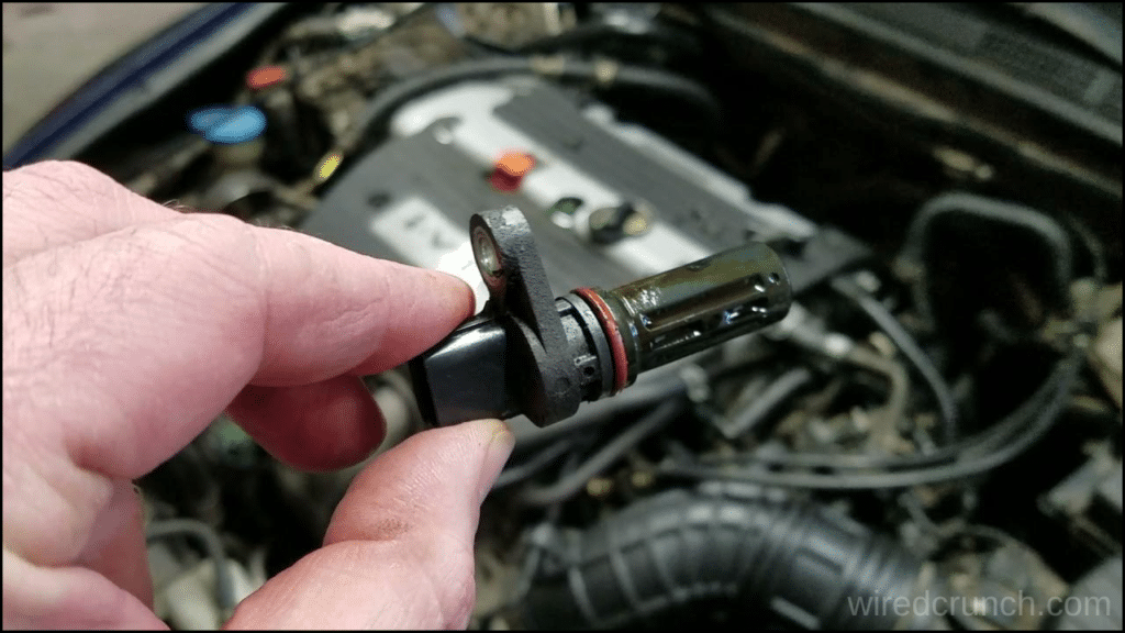
2. Locate the Camshaft Sensor
If there’s an engine cover, you might need to remove it first. Then, locate the camshaft sensor, which can typically be found on the timing cover, cylinder head, or side of the engine block. It’s usually mounted near the top and has a wiring connector attached to it, which may contain two, three, or four wires.
3. Remove the Connector
Typically secured in place to avoid movement, the connector is fastened with a bolt or screw. Undo the fastener and carefully disconnect the connector to avoid damaging the plastic parts.
4. Remove the Sensor
Proceed by removing the fasteners that secure the sensor to the engine. Typically, this involves removing two bolts. Ensure to keep these bolts safe, as they are not included with the new sensor.
5. Remove the Cam Sensor
Carefully lift the sensor out of the engine, ensuring to also remove the O-ring seal from the hole in the engine block. Sometimes, a firm wiggle and twisting motion may be necessary to release it. Avoid prying on the sensor to prevent breakage, as this could complicate the removal process significantly.
6. Install a New O-Ring Seal
The O-ring prevents oil from leaking out of the sensor’s hole and keeps dirt out. Be sure to install a new O-ring in the engine block’s hole.
7. Install the Sensor
Place the new sensor in its original orientation in the engine and secure it using the two bolts. Use the appropriate torque specification to avoid damaging the new part. Reconnect the sensor’s wiring connector and then reconnect the negative battery cable.
8. Clear Existing Codes
Utilize a code reader to clear the Check Engine light and prevent old codes from causing future problems. Start the engine and, if your code reader includes a monitoring feature, ensure there are no new or pending codes and that the cam sensor is functioning correctly.
Conclusion
Understanding the camshaft position sensor diagram is essential for grasping its role in monitoring the camshaft’s rotation and the timing of valve operations. Typically positioned above the camshaft’s notched ring, these sensors utilize magnetic fields to generate an AC electrical signal. Working in tandem with the crankshaft position sensor, they accurately determine the engine’s timing, crucially identifying the top dead center during the compression stroke. This article has covered the definition, functions, diagram, working principle, and symptoms of a faulty camshaft position sensor. I hope this reading has been informative. If you found it helpful, please share it with others. Thank you for reading, and see you next time!
Frequently Asked Questions (FAQs)
How to reprogram the camshaft position sensor?
A bad camshaft position sensor cannot be reset, so you’ll need to swap it out for a new one instead. Check your owner’s manual to find the location of the camshaft position sensor. It is usually attached to the engine or the cylinder head, but it varies based on the make and model.
Do you have to disconnect the battery to change the camshaft position sensor?
Disconnect your negative battery cable. This should be done any time you work with sensors or electrical components. It may be easiest to remove and replace the camshaft sensor from under your vehicle, but it can also be done from the top by removing the air filter housing.
Why do I still get a code when I change my camshaft sensor?
Usually, when you have multiple misfires and a cam sensor code present, it’s an indicator that there is a problem with the cam timing. Especially when you replace the sensor and the issue is still coming up. This may be a problem with the variable timing on the camshaft gear causing the problem.
How long do camshaft position sensors last?
Camshaft position monitors are meant to last as long as the car does, but that doesn’t always happen.
Does a camshaft make noise?
Rather, camshaft grinding typically can be traced back to a ticking or tapping sound. These sounds are often intermittent, which can make them a bit difficult to catch, so when you do notice them, have them inspected as quickly as possible.
READ MORE:
4 Wire O2 Sensor Wiring Diagram Nissan Explained
I have a professional background with a Diploma in Information Communication Technology, which brings a blend of technical expertise and creative flair to my writing. Currently, I serve as a writer for Creativeoutrank LLC and contribute to their various websites.
I’m writing is a ref... Read more