Discover a step-by-step guide to understanding the 3 wire throttle position sensor wiring diagram. Perfect for DIY enthusiasts and mechanics alike. Understanding the wiring of a Throttle Position Sensor (TPS) can be a daunting task, especially when the manufacturer doesn’t provide the necessary information. As someone who has spent countless hours under the hood, I know how frustrating it can be to figure out the correct wiring for a 3 wire throttle position sensor.
This guide is designed to help you navigate the complexities of the 3 wire throttle position sensor wiring diagram, ensuring that you can get your vehicle back on the road with minimal hassle. Whether you’re a seasoned mechanic or a DIY enthusiast, this guide will provide you with the step-by-step instructions needed to accurately wire your TPS.
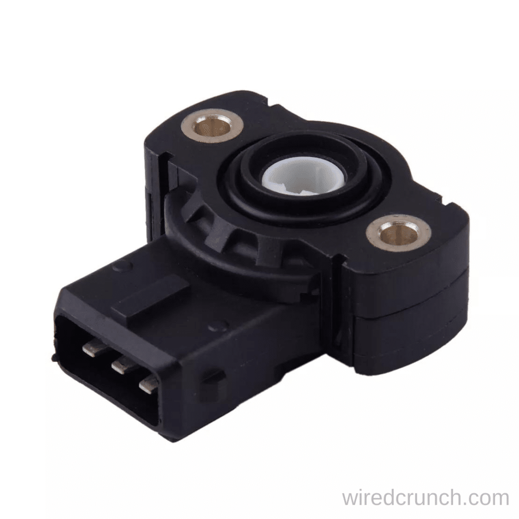
Table of Contents
What is a Throttle Position Sensor (TPS)
The Throttle Position Sensor (TPS) is essential for the engine management system, providing information about the throttle opening angle. This data is crucial for controlling various engine functions, including fuel and ignition calculations, detecting idle conditions, and making adjustments during rapid throttle changes. The TPS works by offering a varying resistance output based on the throttle position.
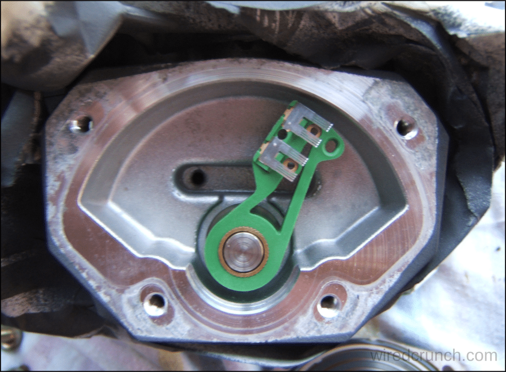
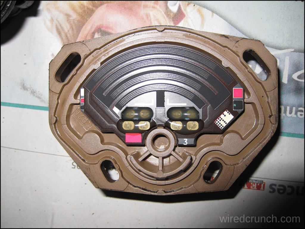
The Engine Control Unit (ECU) supplies 5V to one end of the strip and signal ground to the other, with the wiper sending the signal back to the ECU. The TPS typically has a resistance range from around 200 ohms to 4000 ohms, corresponding to a voltage signal from approximately 0.50V at closed throttle to 4.00V at wide open throttle. The images below illustrate the internal components of a TPS, showing the wiper and strip.
The wiper side of the Throttle Position Sensor (TPS)
The resistive strip side of the Throttle Position Sensor (TPS)
How to Test if the 3 wire throttle position sensor wiring diagram is correct
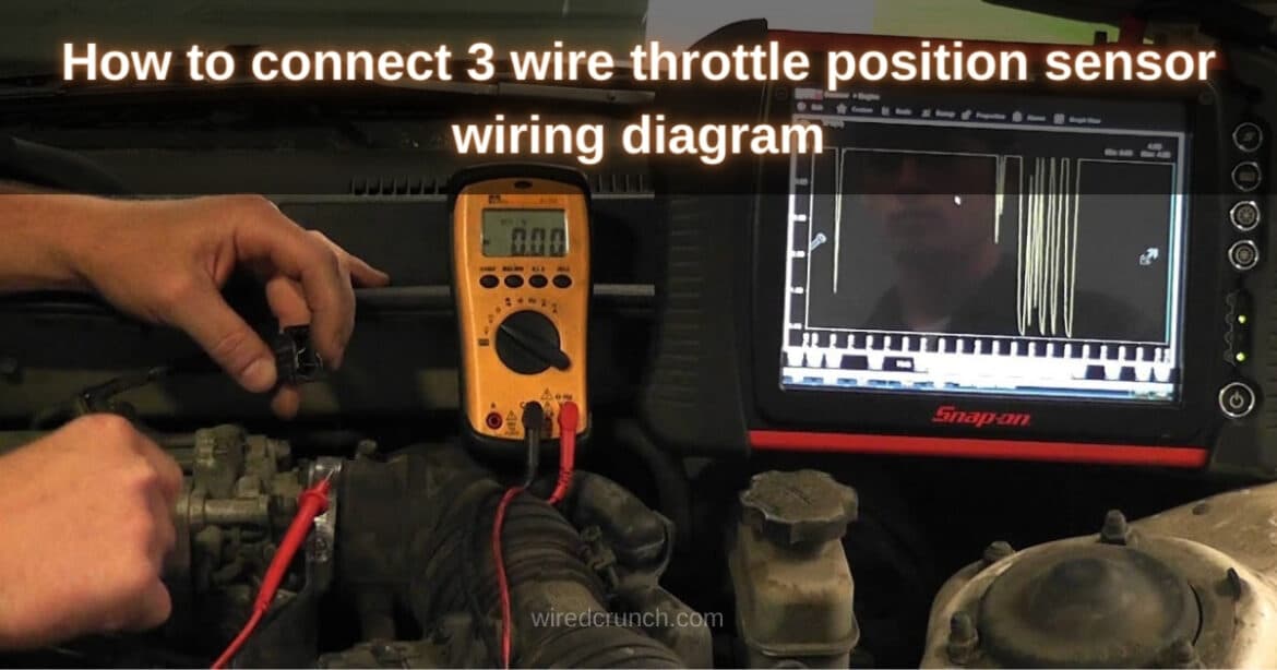
When you encounter a Throttle Position Sensor (TPS) with unknown wiring, it’s relatively easy to perform simple tests to determine the correct connections. All you need is a multimeter capable of measuring resistance. In this example, we have a random TPS with pins labeled 1, 2, and 3 for easy reference.
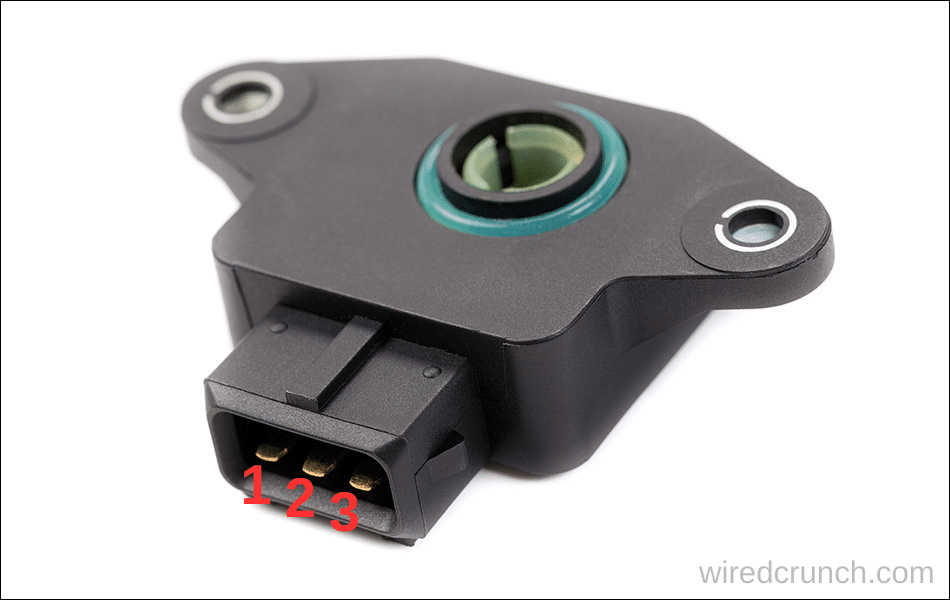
First, use the multimeter to test which pins are the 5V and the Ground. By eliminating these, you can identify the Signal pin. After finding the Signal pin, perform a second round of testing to determine which pin is 5V and which is Ground.
Explaining The Signal Pin
The key to identifying the Signal pin is to first identify the two pins that are not the Signal pin. In other words, you need to determine which two pins are the 5V and Ground.
To carry out this test:
- Set your multimeter to read resistance in the k-ohm range.
- Select any two TPS pins to test and place the probes securely on them.
- Move the TPS through its full range and observe the resistance.
- Look for a pair of pins where the resistance does not change as the TPS moves. If the resistance changes, select another pair to test.
- When you find a pair where the resistance stays constant, these are the 5V and Ground pins.
- The remaining pin is the Signal pin.
Explaining 5V and Ground Pins
Now that we know which pin is the Signal, we need to identify the 5V and Ground pins from the remaining pair. If you get this wrong, the voltage signal sent to the ECU will be inverted. However, this isn’t a big issue for Haltech ECUs, as they can still be calibrated correctly even if the voltage is inverted.
To carry out this test:
- Place one probe of the multimeter on the Signal pin.
- Place the other probe on one of the remaining pins and note the resistance.
- Repeat the test with the probe on the Signal pin and the other probe on the last pin, noting the resistance.
- The pin with the lowest resistance is the 5V.
- The pin with the highest resistance is the Ground.
Adjusting the TPS in ESP
Calibration must be performed when a TPS is used with your Elite ECU for the first time, if the throttle stop has changed, or if the TPS has been moved.
To calibrate the Throttle Position Sensor (TPS), you must be online with your Elite ECU:
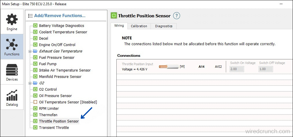
1.Navigate to the Main Setup menu, then go to Functions, and select the Throttle Position Sensor section.
2.Open the Calibration tab.
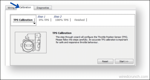
3.Press the Start button to begin the calibration.
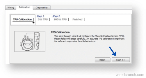
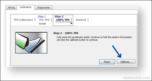
4.Make sure the throttle is fully closed, then press the Calibration button to record the voltage for 0% TPS.

5.Fully open the throttle and press the Calibrate button again to record the voltage for 100% TPS.
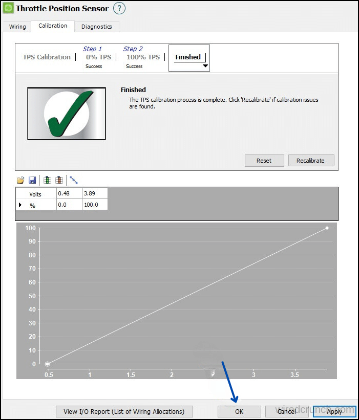
6.You can make a note of the voltages recorded for 0% and 100% TPS. If they seem reasonable, press OK, and your calibration is complete.
Conclusion
Understanding and correctly wiring a 3 wire throttle position sensor is crucial for optimal engine performance. By following the steps outlined and using a 3 wire throttle position sensor wiring diagram, you can ensure accurate readings and proper ECU calibration. Whether you’re a seasoned mechanic or a DIY enthusiast, these guidelines will help you effectively manage your TPS wiring needs.
Frequently Asked Questions (FAQs)
What are the three wires on a throttle positioning sensor?
To identify the 0V (signal ground) and +5V wires, use an ohmmeter or set a multimeter to measure resistance (‘Ω’). Look for the two wires that maintain a constant resistance of approximately 5kΩ, even when the TPS spindle is rotated. The third wire, which shows a varying resistance, is the Signal wire.
What is the voltage of the throttle position sensor?
While the voltages for throttle position sensors can vary by manufacturer, many sensors are non-adjustable. Typically, the voltage ranges from 0.5 to 1.0 volts at idle and increases to 4.0 volts or higher when the throttle is fully open.
What is normal TPS voltage at idle?
Some manufacturers provide an ideal range for the throttle position sensor, which is useful for calibrating a new sensor or recalibrating an old one. For instance, they say 0.5 V for idle and 4.5 V for full throttle (WOT).
How to convert 3-wire to 2-wire sensor?
There are various methods to convert a typical three-wire device into a two-wire output. One of the simplest ways is to use a pull-up resistor (RLOAD) tied between the output pin of the RR122-1B13-511 and its VDD pin.
What is yellow TPS cable used for?
Switch is a 3 core TPS cable designed specifically for lighting applications and ease of identification with its yellow sheath. It is also used for general domestic, commercial and industrial applications for fixed applications.
READ MORE:
How Much Does it Cost to Fix Abs Sensor
I have a professional background with a Diploma in Information Communication Technology, which brings a blend of technical expertise and creative flair to my writing. Currently, I serve as a writer for Creativeoutrank LLC and contribute to their various websites.
I’m writing is a ref... Read more