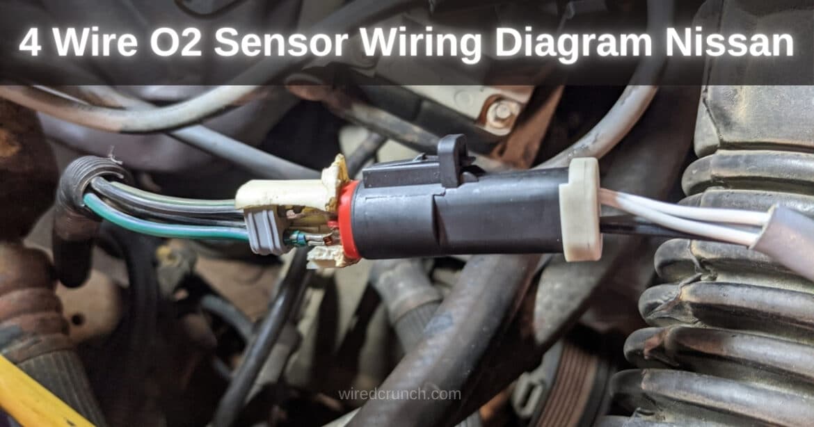
Discover the essentials of the 4 Wire O2 Sensor Wiring Diagram Nissan vehicles. This guide provides clear instructions and diagrams for enthusiasts and mechanics. Modern cars, including those from Nissan, are equipped with 4-wire oxygen sensors, which provide critical data to the engine control unit (ECU). This data allows the ECU to make real-time adjustments to the air-fuel mixture, ensuring optimal performance and fuel efficiency. Grasping the wiring and functionality of these sensors is crucial for both car enthusiasts and mechanics.
This article delves into the intricacies of the 4 Wire O2 Sensor Wiring Diagram Nissan, offering a comprehensive wiring diagram guide for Nissan vehicles.
Whether you’re a DIY enthusiast looking to perform maintenance or a professional mechanic needing a detailed reference, this guide will equip you with the knowledge you need to navigate the complexities of these sensors effectively.
Table of Contents
Functions of the 4 Wire O2 Sensor Wiring Diagram
The 4 Wire O2 Sensor plays a crucial role in a vehicle’s emission control system by using four distinct function wires. These wires are the positive wire, negative wire, heating wire, and signal wire. The positive and negative wires, usually white, connect to the sensor’s heating coil power source and ground wire. Their role is to supply power to the heating element, enabling the sensor to reach its operational temperature of around 300 degrees Celsius quickly. This ensures accurate oxygen measurement during operation.
The remaining two wires are signal wires: one is black, and the other is gray, functioning as the signal ground wire. These wires connect to the engine computer and the vehicle’s power supply. The signal wires transmit the oxygen concentration information detected by the sensor to the engine computer. This information helps adjust the engine’s air-fuel ratio, ensuring it combusts at the optimal ratio of 14.7:1. This is essential for improving fuel efficiency and reducing exhaust emissions.
Positive Wire:
The 4 Wire O2 Sensor connects to two porous platinum (Pt) electrodes on either side of a ceramic tube. When the sensor reaches a certain temperature, the differing oxygen concentrations on each side cause oxygen molecules on the high-concentration side to be adsorbed onto the platinum electrode. These molecules form oxygen ions (O2-) by combining with electrons, making the electrode positively charged. The O2- ions migrate to the low-oxygen-concentration side (the exhaust side) through oxygen ion vacancies in the electrolyte, which causes the electrode to gain a negative charge and create a potential difference.
Signal Wire:
The signal wire functions under different air-fuel ratio conditions. When the air-fuel ratio is low (rich mixture), there is less oxygen in the exhaust, resulting in fewer oxygen ions on the outer side of the ceramic tube, creating an electromotive force of about 1.0V. When the air-fuel ratio is at the ideal stoichiometric ratio of 14.7:1, the electromotive force on both sides of the ceramic tube is around 0.4V to 0.5V. This electromotive force acts as the reference potential.
Heating Wire:
When the air-fuel ratio is high (lean mixture), the exhaust has more oxygen, resulting in a smaller difference in oxygen ion concentration between the interior and exterior of the ceramic tube. The 4 Wire O2 Sensor detects this condition, resulting in a very low electromotive force that approaches zero. This low-voltage signal helps the engine control unit adjust the air-fuel mixture for optimal performance and efficiency.
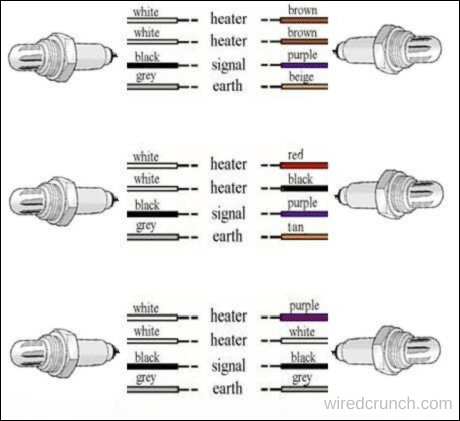
4 Wire O2 Sensor Wiring Diagram Nissan Diagram
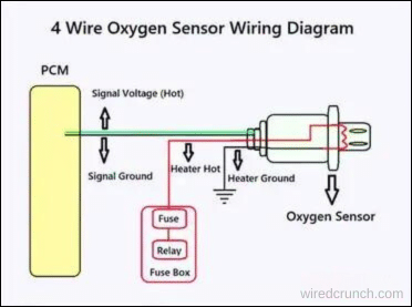
Color code for the 4 Wire O2 Sensor cable
- Heater+ (Positive): Typically white or white with a stripe.
- Heater- (Negative/Ground): Typically white or white with a stripe, sometimes gray.
- Signal Output Wire: Typically black.
- Ground Wire: Typically gray.
How Does a 4 Wire O2 Sensor Work
A 4-wire O2 sensor monitors the oxygen levels in a vehicle’s exhaust gases and relays this data to the engine control unit (ECU) or engine control module (ECM). The ECU uses this feedback to adjust and optimize the air-fuel mixture, ensuring efficient combustion and reducing emissions. This process helps maintain the engine’s performance and improves fuel efficiency.
- Heating Element: An integrated heater keeps a high operating temperature, ensuring accurate readings.
- Gas Diffusion: Exhaust gases flow through a gas-permeable ceramic element at the sensor’s tip.
- Voltage Signal: Oxygen ions travel across the ceramic element, generating a voltage signal corresponding to oxygen levels.
- Signal Output: The signal is transmitted to the vehicle’s ECU for real-time monitoring.
- ECU Feedback: The ECU adjusts the air-fuel mixture according to the signal to enhance engine performance and minimize emissions.
Troubleshooting 4 Wire O2 Sensor Wiring Issues
Step 1: Identifying Common O2 Sensor Wiring Problems
Incorrect wiring connections
Damaged or frayed wires
Corrosion or rust on cables or connectors
A malfunctioning or faulty O2 sensor
Step 2: Signs of O2 Sensor Wiring Issues
Lower fuel efficiency
Decreased engine performance and acceleration
Check engine light turning on
Presence of error codes or diagnostic trouble codes (DTCs)
Step 3: Methods for Diagnosing O2 Sensor Wiring Issues
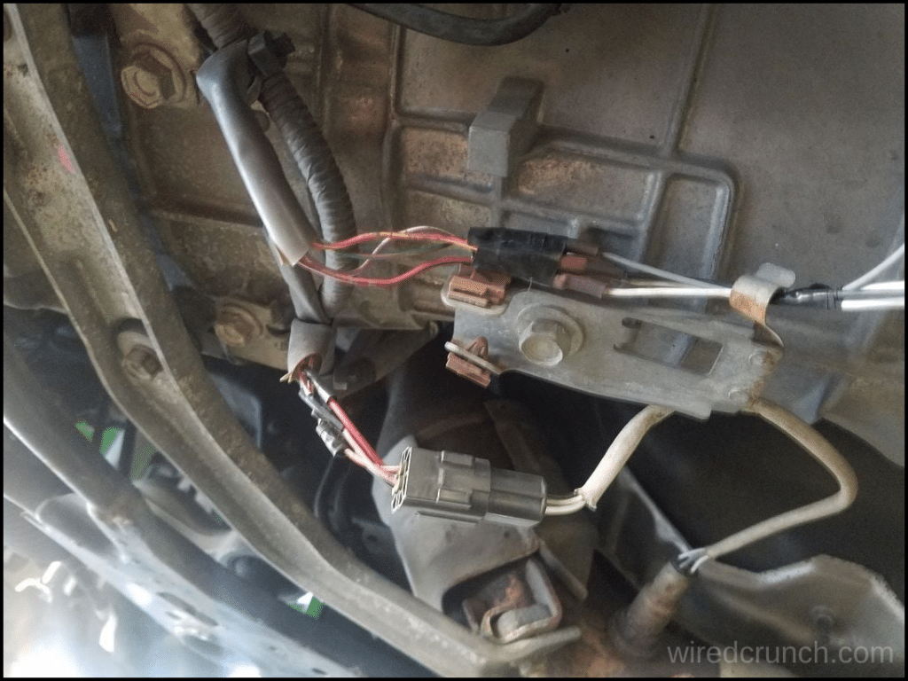
Start with a visual inspection of the O2 sensor and its wiring.
Use a multimeter to check wire continuity and resistance.
Employ an OBD-II scanner to detect error codes or DTCs that may indicate wiring problems.
How to test 4 Wire O2 Sensor
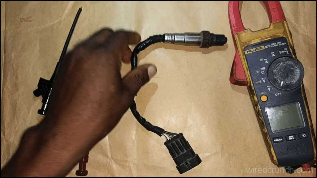
Testing a 4 Wire O2 Sensor is straightforward with the right tools and steps. Follow this guide to test a 4 Wire O2 Sensor:
Tools and Materials
- Multimeter
- Safety goggles and gloves
- Vehicle service manual (for reference)
Steps
Safety Precautions:
- Park the vehicle on a flat, stable surface.
- Wear safety goggles and gloves to protect your eyes and hands.
Find the O2 Sensor:
- Check your vehicle’s service manual to locate the O2 sensor. It’s usually in the exhaust system, either before or after the catalytic converter.
Disconnect the Sensor:
- Unplug the electrical connector from the O2 sensor. You may need to remove a connector clip or simply unplug the wires, depending on your vehicle.
Set Up the Multimeter:
- Power on your multimeter and adjust it to the voltage (V) mode. For most O2 sensors, choose the DC voltage range of 0-1V.
Probe the Wires:
- Identify the four wires in the wiring harness: Heater+, Heater-, Signal, and Ground. Use the sensor’s color code or check your vehicle’s service manual if necessary.
- Attach the multimeter probes to the Signal wire and the Ground wire, ensuring the positive probe goes to the Signal and the negative probe to the Ground.
Check for Voltage:
- Start the vehicle or turn the ignition to the “On” position and watch the multimeter reading. A functioning O2 sensor should show a fluctuating voltage between about 0.1V and 0.9V.
- The voltage should quickly switch between rich (higher voltage) and lean (lower voltage) air-fuel mixtures.
Check the Heater Circuit:
- Detach the multimeter probes from the signal and ground wires.
- Connect the probes to the Heater+ and Heater- wires instead.
- Take a voltage reading across these wires. A working O2 sensor should show a voltage reading, usually around 12V, indicating the heater circuit is receiving power.
Visual Inspection:
- Inspect the sensor closely for any physical damage or contamination, such as soot or oil deposits on the sensor tip.
Reconnect the Sensor:
- Once testing is complete, plug the O2 sensor back into its electrical connector.
Clear Error Codes (if necessary):
- If you tested the O2 sensor because of a fault code, you might need to use an OBD-II scanner to clear the error codes from the vehicle’s ECU.
Are all 4 Wire O2 Sensors the same?
When it comes to a 4 Wire O2 Sensor, it’s important to know that not all of them are the same. Even though they generally perform similar functions, there can be differences in their specifications, designs, and compatibility depending on the manufacturer, as well as the vehicle’s make and model. For instance, I once replaced a 4 Wire O2 Sensor on my car, and I had to ensure it was the right fit for my vehicle’s make, model, and engine type. Selecting the correct oxygen sensor is crucial to ensure proper performance and avoid potential issues.
Conclusion
Understanding the 4 Wire O2 Sensor Wiring Diagram Nissan is essential for proper installation and performance. Make sure to choose the right sensor for your specific vehicle make, model, and engine type to ensure everything runs smoothly. Following the correct wiring diagram will help you avoid issues and keep your Nissan running efficiently.
Frequently Asked Questions (FAQs)
How many volts does an O2 sensor need?
A properly functioning oxygen sensor will show a rapidly fluctuating output voltage between approximately 0.1 and 1.0 volts. The duration for the voltage to transition from 0.1 V to 1.0 V (known as the lean to rich response time) should be approximately 300 milliseconds.
Why is 4-wire better than 2-wire?
Provides the highest accuracy by eliminating the effects of lead wire resistance on the measurement.
What is the difference between 4-wire and 5-wire oxygen sensors?
The 5-wire is a wideband sensor, the 4-wire is a narrowband. They communicate with the ECU completely differently.
Why does my car have 4 O2 sensors?
Every catalytic converter is required to have a couple of oxygen sensors. So if you have a single exhaust system, you probably have one catalytic converter and, thus, two oxygen sensors. Cars with double exhaust pipes, meanwhile, will be fitted with a total of four oxygen sensors.
How do you disconnect O2 sensor wires?
To remove it, locate the small tab on the end of the plug. While pushing the tab down, pull the plug back by hand. If you’re having a hard time unplugging the sensor wire, push the tab down with a flathead screwdriver as you pull the connection back with your free hand.
READ MORE:
How To Connect 3 Wire Throttle Position Sensor Wiring Diagram
I have a professional background with a Diploma in Information Communication Technology, which brings a blend of technical expertise and creative flair to my writing. Currently, I serve as a writer for Creativeoutrank LLC and contribute to their various websites.
I’m writing is a ref... Read more