BH1750 Ambient Light Sensor with Arduino
The BH1750 is a 16-bit surrounding light sensor. Here, you can study how to use the BH1750 ambient light sensor with an Arduino board. The sensor hangs up with the microcontroller using a 12C communicating protocol.
In this guide, you can learn how to connect the sensor to the Arduino board. Installing the relevant libraries and using a simple design to get the sensor readings in the Serial monitor.
The below topics are covered by the article.
- Introduction of the BH1750 Ambient Light Sensor
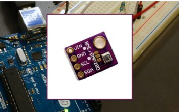
- BH1750 Pinout
- BH1750 I2C Interface
- Examples of the BH1750 Ambient Light Sensor with Arduino.
Introducing BH1750 Ambient Light Sensor
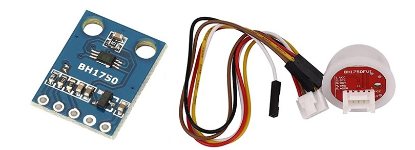
The BH1750 is a 16-bit light sensor that is transmitted via I2C protocol. It provides radiance measurements in lux. It counts a minimum of 1 lux and a maximum of 65535 lux.
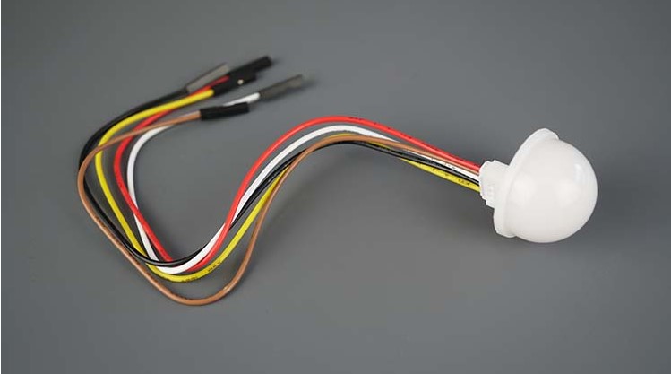
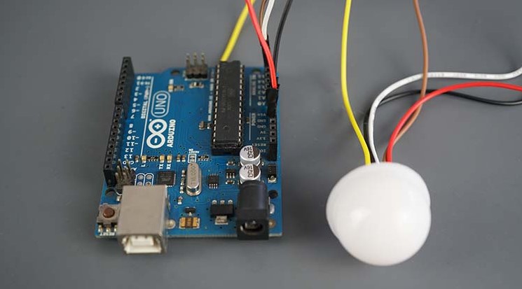
The sensor can be in various breakout board patterns. See the below-given pictures. Both images symbolize a BH1750 sensor.
BH1750 Features
There is a list of BH1750 sensor attributes. For more information search from the BH1750 sensor data list.
- I2C bus Interface
- Shadowy responsibility is roughly human eye reactive
- Very bright for digital converter
- Range: 1 – 65535 lux
- The low current supplied by the power-down methods
- 50Hz / 60Hz Light noise rejecting tools
- It can choose 2 various 12C slave addresses
- Small measurement differences
- It has a small amount of infrared effect
- Support for ongoing measurement mode.
- It supports a one-time measurement mode.
Measurement Modes
The sensor is working with two different measurement types: the ongoing measurement method, and the one-time measurement method. Each of the methods supports three different resolution modes.
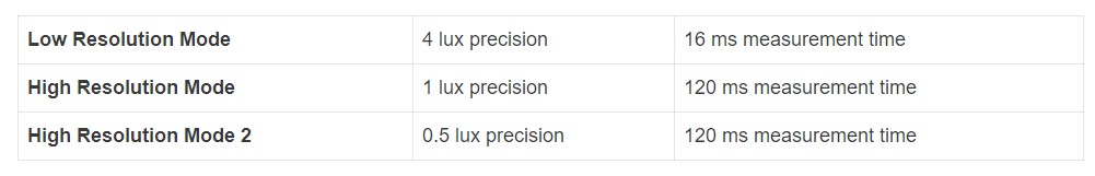
In ongoing measurement mode, the sensor regularly counts the ambient light values. In the one-time counting method, the sensor measures the surrounding light values only one time. After that, it moves to the power mode.
Applications
As The BH1750 is an ambient light sensor that can be used in many projects. For example,
- To identify if it is day or night
- To control or turn on/off LED’s brightness corresponded to the ambient light.
- To control the LCDs and brightness of the screen.
- To identify an LED is to list
BH1750 Pinout
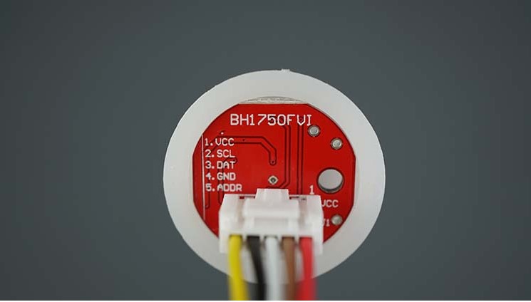
The below table shows the BH1750 Pinout:
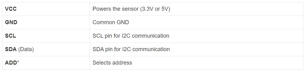
We use the ADD pin to set the 12C sensor location. If the voltage on the pin is lesser than 0.7VCC (pin is left floating or linked to GND) the I2C location is 0x23. But if the voltage is above 0.7xVCC (Pin is linked to VCC), the allocation is 0x5C. As summary,
ADD pin floating or link to GND address: 0x23
ADD pin linked to VCC → address: 0x5C
BH1750 I2C Interface
The BH1750 ambient light sensor aids the 12C interface.
Use the default I2C pins to connect the BH1750 sensor to the Arduino. (12C pins are available for the Arduino UNO. If you use another kind of model check the 12C pins.)
BH1750: Read Ambient Light with Arduino
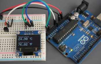
Now you have knowledge about the BH1750 sensor, let’s move on to check it. In this part, we are making a small project that checks the surrounding light and shows it in the Arduino IDE
Parts Required
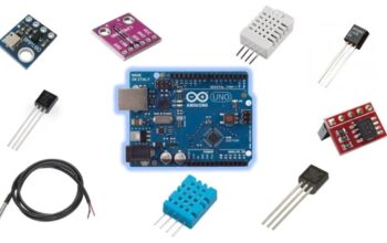
For completing the guide you must follow the below-given parts.
- BH1750 ambient light sensor
- Arduino (refer to Best Arduino starter kits)
- Breadboard (Can be selected)
- Jumper wires (Can be selected)
The previous links can be used or you can directly go to MakerAdvisor.com/tools and get all the parts for the projects for a good price.
Schematic – Arduino with BH1750
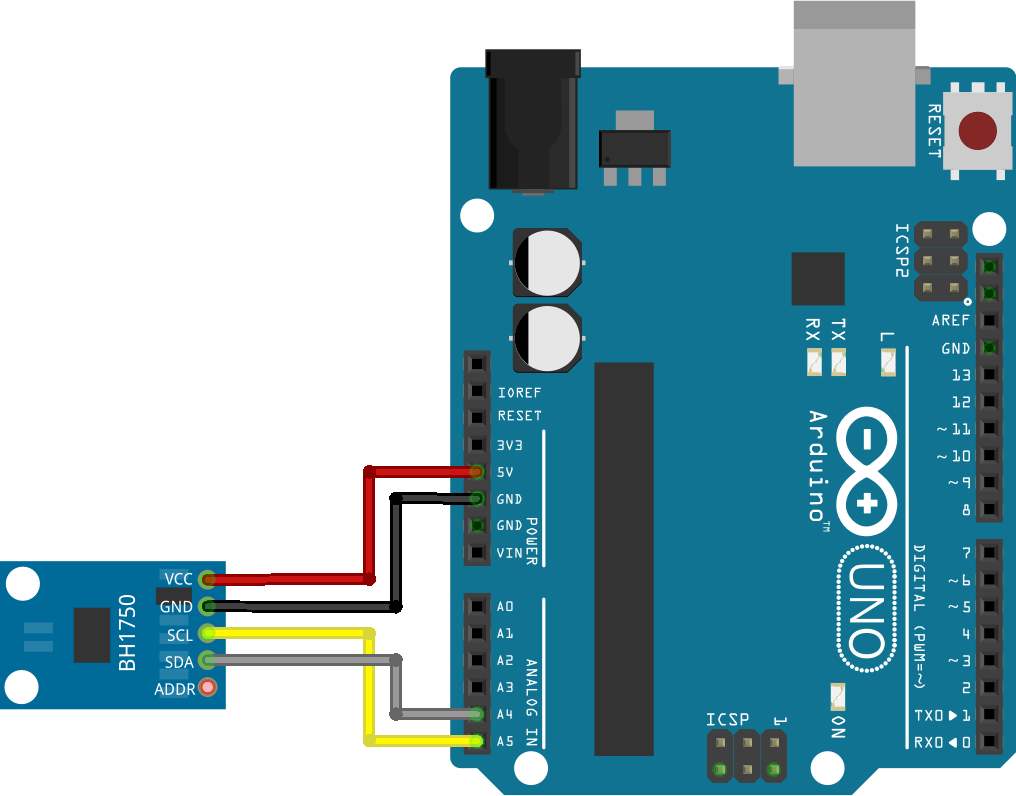
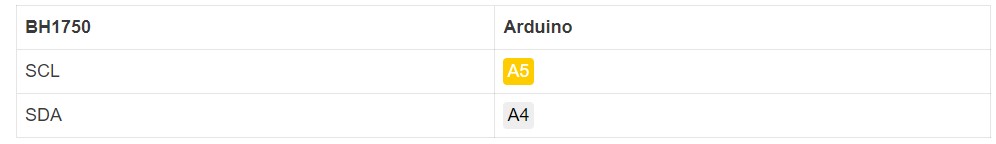
Connect the BH1750 sensor with the Arduino 12C pins. You can refer to the below design.
Follow the next table as well.
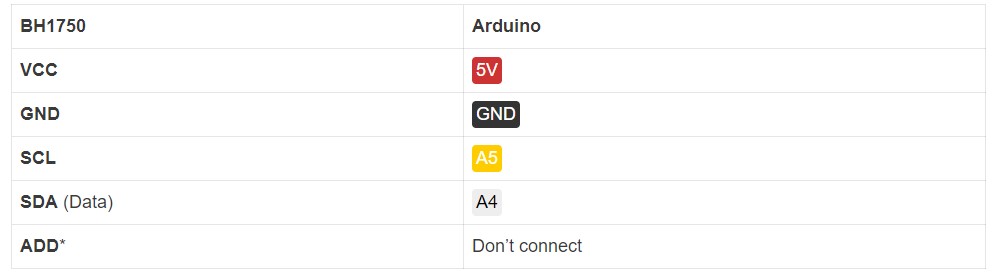
If you do not connect the ADD pin, you select the 0x23 I2C address. Alternatively, connect it to 3.3V to get the 0x5C address.
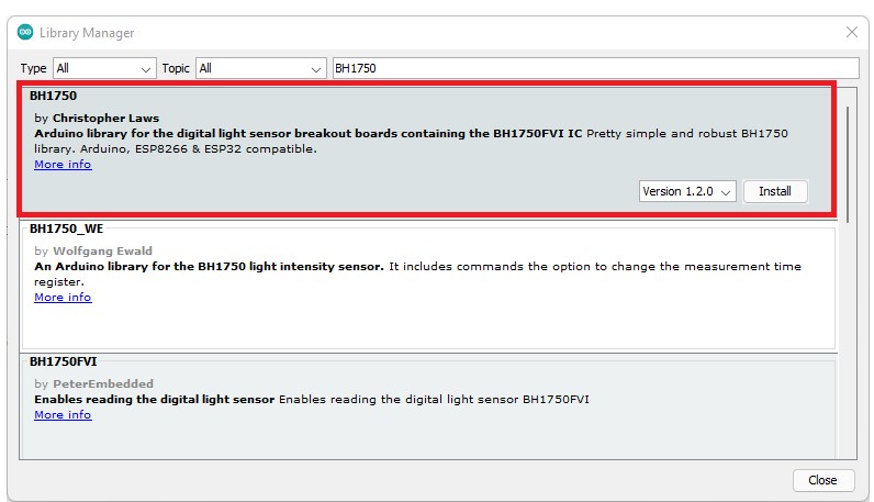
How to Install the BH1750 Library
There are some libraries available for reading from the BH1750 sensor. We are using the BH1750 library by Christopher Laws. It is consistent with the ESP32, ESP8266, and Arduino.
Open the Arduino IDE and head to Sketch > Include Library > Manage Libraries. After that, the Library manager will open.
Search the BH1750 on the search box and next install the BH1750 library by Christopher Laws.
Code – Reading BH1750 Ambient Light Sensor
Get the below code to the Arduino IDE. This code clearly recorded the Ambient light in lux and gives the values on the serial monitor. It is the instance code obtained from the library named BH1750test. You can check it by heading to File > Examples > BH1750 > BH1750test.
The library has more examples that are good to search for.
How the Code Works
First, we have to enter the relevant libraries. The Wire. h library uses the 12C communication protocol, and the BH1750.h library reads from the sensor.
#include <Wire.h>
#include <BH1750.h>
Next, we are creating a BH1750 object named lightMeter.
BH1750 lightMeter;
In the setup() format the Serail Monitor at a baud rate of 9600.
Serial.begin(9600);
Format the 12C communication protocol. It begins with a 12C communication protocol. If you are looking to use any other 12C pin, send them to begin() method. Follow the step Wire.begin(SDA, SCL).
Wire.begin();
Format the sensor by giving the begin() method on the BH1750 object (lightMeter)
lightMeter.begin();
In the loop() a variable named lux is created, it is recording the luminance value. To output ,the value, call the readLightLevel() method on the BH1750 object (lightMeter).
float lux = lightMeter.readLightLevel();
At last, it shows the measurement on the serial monitor.
Serial.print(“Light: “);
Serial.print(lux);
Serial.println(” lx”);
It prints the new readings every second.
delay(1000);
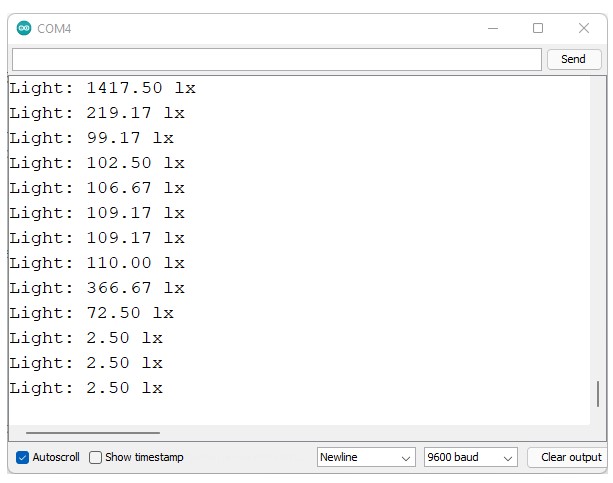
Demonstration
Now, upload the code to the board. First link the board to the computer. Next head to the Tools > Board and point to the Arduino board that you use. Go to Tools > Port and choose the COM port that the board is connected to. At last press the upload button.
After you have uploaded the code, go to the Serial monitor and open it at a baud rate of 9600.
New radiance outputs are printed in the Serial monitor.
Other Useful Functions
The library that we use with the BH1750 sensor gives some other examples that demonstrate other important functions and features. Check them by the BH1750 library example.
Setting Measurement Mode
Default the library has got a steady high-resolution measurement mode. You can edit it by changing the necessary measurement modes into the begin() method when formatting the sensor. As an example,
lightMeter.begin(BH1750::CONTINUOUS_HIGH_RES_MODE)
There are some available modes mentioned.
- BH1750_CONTINUOUS_LOW_RES_MODE
- BH1750_CONTINUOUS_HIGH_RES_MODE (default)
- BH1750_CONTINUOUS_HIGH_RES_MODE_2
- BH1750_ONE_TIME_LOW_RES_MODE
- BH1750_ONE_TIME_HIGH_RES_MODE
- BH1750_ONE_TIME_HIGH_RES_MODE_2
Wrapping Up
In this guide, you could learn how to use the BH1750 ambient light sensor with the Arduino Uno. It is very easy to use the sensor. It has got a 12C communication protocol and makes it easy to set the wires. And as well the library gives the methods to have the readings.
It is sure that this article is very important for you.
Frequently asked questions
How does the ambient light sensor work?
The device marks the ambient light level and dims the screen as required. Doing this prevents the screen from being too dark when the device is used outside during the day or too bright when the user’s pupils are adjusted for eyesight in a dark room.
Is the ambient light sensor an LDR?
The sensor is a radioshack resistor model 276-1657 light-dependent resistor (LDR), The resistance model 276-1657 varies with the ambient light power.
How to use a BH1750 Arduino?
First, attach one of your five jumper wires to the 5v (+) pin on your Arduino board and the VCC (+) pin of the sensor. Now connect the GND (-) pin of your BH1750 sensor to one of the GND (-) pins on your Arduino with a different jumper wire.
Recommendations:
Guide for BMP388 Altimeter with Arduino (Pressure, Altitude, Temperature)
K-Type Thermocouple with MAX6675 Amplifier
Arduino with Load Cell and HX711 Amplifier (Digital Scale)